Arduino Uno R3 Elegoo LED Sequential Control Project
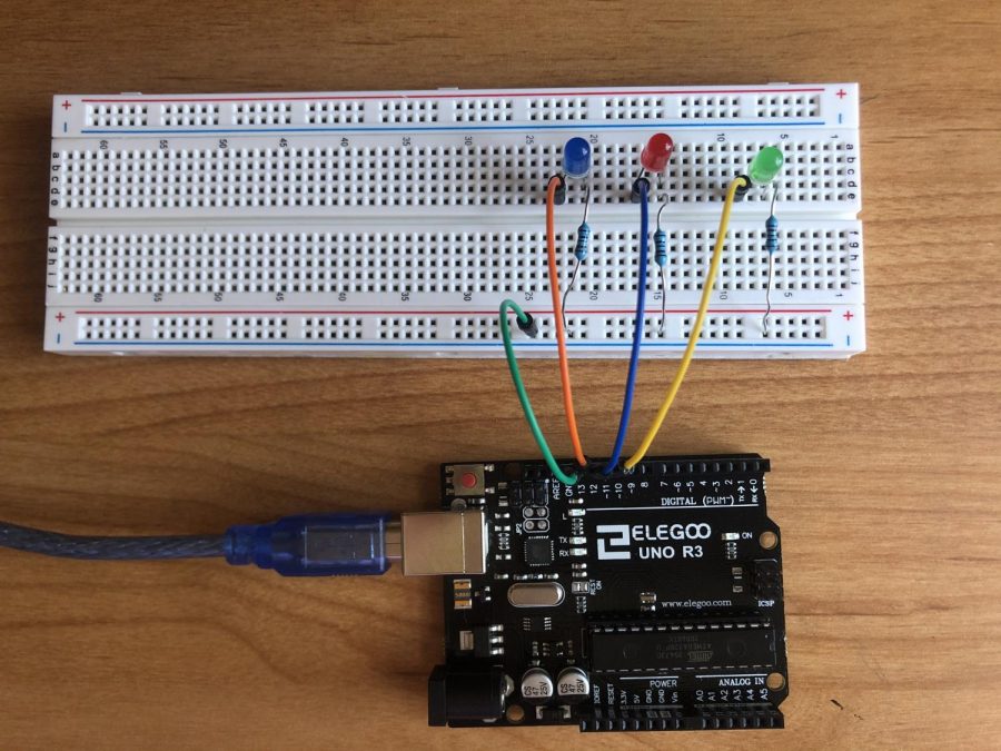
Today I will be making the arduino uno R3 elegoo LED sequential control project. The materials that you will need for this project are, one uno R3 controller board, one 830 tie-points breadboard, one USB cable, three LED lights, three resistors, and four breadboard jumper wires. The steps for this project will be located below so you can follow along.
Step 1: Pick one of your wires and connect it to the GND (ground) pin on your uno R3 controller board and after that connect the other end of the same wire to the negative rail on the 830 tie-points breadboard.
Step 2: Connect all of the resistors to the 830 tie-points breadboard with one leg of each resistors connected to the negative rail and connect the other ends of the resistor to a horizontal line to the end that is connected to the negative rail (do this step with all 3 resistors).
Step 3: Now connect the LED lights to the 830 tie-points breadboard with the negative lead (negative lead is the shorter lead) in the same horizontal rail as the resisters and connect the positive lead (positive lead is the longer lead) to a adjacent rail (do this step with all 3 LED lights).
Step 4: Get your second wire and connect it to pin “13” on your uno R3 controller board and after that connect the other end of the wire to the horizontal line which the positive lead of the right LED light is in, on the 830 tie-points breadboard.
Step 5: Get your third wire and connect it to pin “12” on your uno R3 controller board and after that connect the other end of the wire to the horizontal line which the positive lead of the center LED lights is in, on the 830 tie-points breadboard.
Step 6: Get your fourth wire and connect it to this pin “~11” on your uno R3 controller board and after that connect the other end of the wire to the horizontal line which the positive lead of the left LED lights is in, on the 830 tie-points breadboard.
Step 7: Now connect your uno R3 controller board to your computer using a USB cable.
Step 8: After your computer is connected to the uno R3 controller board you will need to instal the code which will be located below.
If your LED lights are blinking in a sequential format then you are finished with making the arduino uno R3 elegoo LED sequential control project.
Code for project –
/* A simple program to sequentially turn on and turn off 3 LEDs */
int LED1 = 13;
int LED2 = 12;
int LED3 = 11;
void setup() {
pinMode(LED1, OUTPUT);
pinMode(LED2, OUTPUT);
pinMode(LED3, OUTPUT);
}
void loop() {
digitalWrite(LED1, HIGH); // turn on LED1
delay(200); // wait for 200ms
digitalWrite(LED2, HIGH); // turn on LED2
delay(200); // wait for 200ms
digitalWrite(LED3, HIGH); // turn on LED3
delay(200); // wait for 200ms
digitalWrite(LED1, LOW); // turn off LED1
delay(300); // wait for 300ms
digitalWrite(LED2, LOW); // turn off LED2
delay(300); // wait for 300ms
digitalWrite(LED3, LOW); // turn off LED3
delay(300); // wait for 300ms before running program all over again
}