How to Use a CNC Shark HD4 and The Software for it
Software
Material Set Up
The software used to create 2D and 3D models for the CNC shark to make is made by Vectric. The software I use is called Aspire 10.0. First click on the Windows icon along your taskbar. Then find “Aspire” with number(s) after it, “Aspire” may be under a folder called “My Applications”. Click Aspire and then it should pop up, it may take some time. Once it is open, click “create a new file”. Then you need to set your material size, which includes the width height and thickness. One of the more important ones to have correct is your thickness, if your thickness is thicker than the piece of wood that you are carving you may end up damaging your machine bed. Once you set your material sizes set your Z-zero position, this will vary based on what your doing, but you should set it to material surface, instead of machine bed. Then set your XY data position (the Zero for both your X and Y axes), which will be where your drill bit should be set before you start to drill. For signs you should do one sided jobs. Modeling resolution and appearance do not need to be messed with, because that is for how the 3D generated model looks, and we will get to that later in the article. Press OK once you have done all previous steps.
Vectors and Creating Them
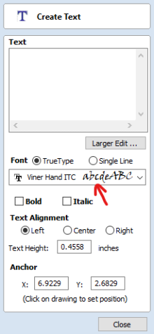 Now that your material is set up it is time to create vectors which are used to create toolpaths. Vectors can be made in many various ways, which include text, polygons, custom polygons, circles, images that you import (which we will not go over), lines, and more. To create text simply press the T with no dotted box around it on the left side of your screen under “create vectors”. Once you have clicked it, then type in your text in the box on the side of the screen, when you type the letters they should appear on the white plane on your screen. To give your text a different look you can change the font of the text by clicking on the box on the left side of your screen that has two Ts, like shown in the image. After you have done that, click close, which will take you back to the screen you were on. To create a custom polygon/polyline, click the zigzag icon and that will open up a menu, from there click on where you want your points to be for the polyline, and then to stop either click “close”, or close the shape. To make a regular polygon, rectangle, or circle, simply click the one that says so by hovering over the icon with your mouse, or by clicking on the icon that looks like what you want to make. To create, simply click and drag to determine the size, or determine the size in the sidebar on the left side. to edit how many sides you want your polygon to have simply click on the box next to “number of sides” and then change the number of sides to the number you want, and then click and drag, or give exact sizes using the sidebar. Drawing a star is similar to drawing a polygon. Mess around with the software to figure more things out. To create a basic 3D shape click on “modeling” and then click “create a shape from vector outlines” and the click on one of the options that are available to create a 3D shape. To create a 3D border click on two vectors that act as a rails, then click on a third vector that acts as a texture/design to go in-between the to other vectors.
Creating a Toolpath
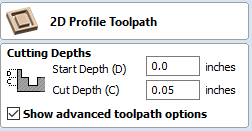 This step called “creating a toolpath” is very important to actually creating what you want. Look at the bar at the top of your screen inside of aspire and look for “toolpaths” and click on it. Once you have done that, click “show toolpaths tab” which should open up a sidebar on the right side of your screen. Then click “material setup” which will give you some options the only thing you need to worry about is the thickness and the start position. Make sure the start position is set to zero for the X and Y axes. Scroll up and set the Z-Zero to the surface of the material. There are three options that I consider basic, the outline, pocket, and V-carve. To start creating a toolpath click on a vector, or multiple vectors(which should show up in a violet or purple if they are selected) then click on one of the options. The outline/profile toolpath option allows you to create a outline of a shape, on either the line, along the outside of the line, or along the inside of the line. A V-carve allows for you to engrave letters. The pocket allows you to cut/drill out a space. All functions will need you to determine how deep you want to carve, which includes the start depth, and the cut depth. If you are engraving o
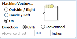 n a piece of wood that isn’t messed with on the side you are cutting on, set the start depth to zero, and then determine how deep you want to cut, make sure you don’t cut through the material unless you want to. You should also select the right bit because results will vary depending of the diameter and type of bit, look at the selection that you physically have and measure to determine what bit you should use. Then click calculate so that the tool path is created, and you can preview the tool path on to the 3D model. Use the 3D rough and finishing toolpath options to create 3D objects/designs. There are other toolpaths which I will not cover in this article. Mess around to find out how to use the other toolpath options.
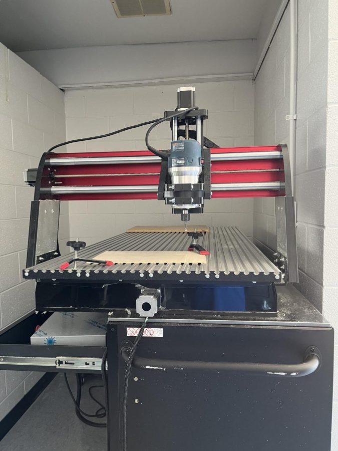
Setting up the Machine
Before messing with the machine, put your piece of wood(or any other material that the machine can handle) where you want it and the direction you want it, then get two or more clamps, slide them into position, and then tighten the clamps down onto the material you are using. Something important is to make sure your clamps are not in a area where the bit will be drilling, otherwise you will damage the clamps. To turn on the machine switch on the switch on the back of the grey box. When you do, the color pendant should turn on, click “Continue” and then click “OK” until you reach a screen with numbers on it, each of the boxes with numbers in it should have a label saying what axis they represent. The Z axis should be set to the surface of the material, and the X and Y should be set to the corner of the material that you choose to be your X and Y zero early on during Material setup. Using the Interface on the pendant move the drill bit where it needs to go, and press “zero xyz” to set the current position of the bit to zero for all axes, making sure that the drilling is accurate.
Safety Information
Make sure the bit is secured and tightened in the right position, make sure your material is the right size, make sure you are wear a face shield, or at least goggles. Make sure you inform who you need to inform.
Related Articles:
https://www.vectric.com/products/vcarve-pro
https://esteemstream.news/wp-content/uploads/2022/05/Shark-HD4-Extended-Owners-Manual.pdf
https://sites.tufts.edu/bray/theshop/cnc-router/shopbot-machine-setup/
Take Action: