Elegoo Arduino R3 – LED Light On/Off Button Project
https://www.arduino.cc/en/Tutorial/BuiltInExamples/Button
Using a button or switch to turn an LED on and off is one of the more simpler projects you can do with the Elegoo Super Starter Kit UNO R3 Project.
Step 1: Materials
- Arduino UNO Elegoo
- Breadboard
- 4 pin Button
- 10K ohm Resistor
- Wires
- (not necessary but different colors make instructions easier)
- 3 Black Wires
- 3 Red Wires
- 1 Blue Wire
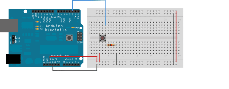
Step 2: Side fghij of the breadboard should be facing your direction. Connect 1 red wire that goes from 5V (positive) on the Elegoo Uno R3 to the the very top of the positive row on the fghij side of the breadboard and one black
wire from GND (negative) the Elegoo Arduino Uno to the negative row on the breadboard also on side fghij.
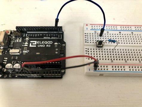
Step 3: Place the 4 pin button in the middle, 2 legs are connected to row e and 2 are connected to row f.
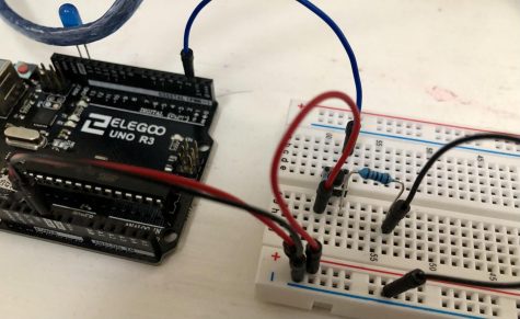
Step 4: Connect 1 blue wire from pin 2 on the Arduino UNO Elegoo to a pin vertical on the left leg of the button on side abcde. Place the 10k ohm resistor on the fghij side with one pin vertical to the button leg and wire .
Step 5: On side fghij, connect 1 red wire from the positive row to the pin that is vertical to the button leg to the left of the resistor. Connect 1 black wire from the negative row to a pin vertical to the right leg of the resistor.
Step 6: Insert the LED into pin 13. The longer pin of the LED is positive and’s called the “anode”. The shorter pin of
the LED is negative and’s called the “cathode”. The anode goes into pin 13 and the cathode goes into GND.
Step 7: Plug the Elegoo UNO R3 into your computer. Send the code into your Arduino UNO Elegoo, it can be found at the bottom of the page at “https://www.arduino.cc/en/Tutorial/BuiltInExamples/Button“
When the button is not pressed there is no connection in the legs of the button, so the pin is connected to the ground through the 10K ohm resistor and we read a LOW. When the button is being pressed there is a connection between the legs of the button and we read a HIGH.
RELATED ARTICLES:
http://vladromanov.com/148/arduino-tutorial-1-digital-inputs-outputs/
https://www.instructables.com/Controlling-LED-by-Button-With-Arduino-Uno-R3/
https://www.arduino.cc/en/Tutorial/BuiltInExamples/Button
https://create.arduino.cc/projecthub/glowascii/button-arduino-basics-5ecffc