Elegoo Arduino Uno R3 – Spaceship Interface Project
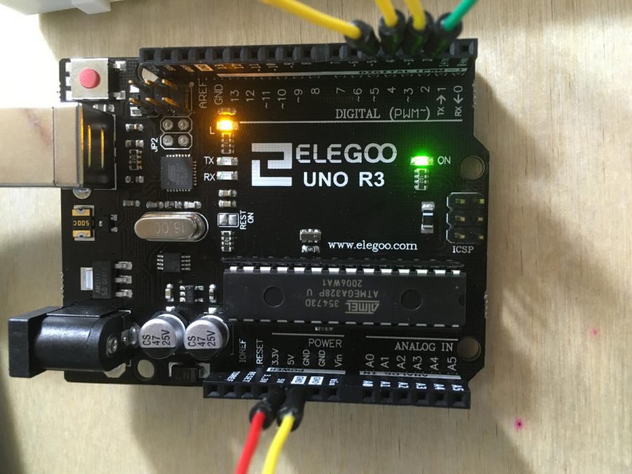
The Spaceship Interface Project is a simple task from Arduino, which you can do on an Elegoo Arduino Uno. You need three 220 OHM resistors, one 10 KIL OHM resistor, five small wires, 2 long wires, three LEDs (two red and one green), and a button.
To make the circuit of your Spaceship Interface Project, insert the red LEDs one space below the middle on each into 36 and 37, as well as 39 and 40. Make sure the longer side of your LED is on the left, in 36 and 39. Attach the green LED into 42 and 43 in your breadboard, with the long side in 42. Put each of the three 220 OHM resistors underneath the LEDs, in spots 37, 40, and 43, two spaces under the LED. Attach the other end of the resistors in the two lane rows, essentially two spaces below where you attached the front of the resistors. Next, add your button to 48 and 50, stretching across the breadboard and on the other “side”. Insert the 10 KIL OHM resistor three spaces under 48, and stretch the resistor two spaces down, into the two lanes as you did with the LED resistors. 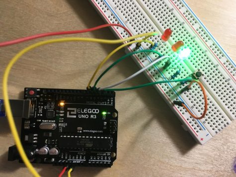
Next, you have to do the wires. Add a small wire three spaces below the left side of each LED. The wire attached to the LED on the farthest left will be inserted into digital pin ~5. The wire under the LED in the middle will be put into digital pin ~4. And the wire under the green LED on the farthest right will be inserted into digital pin ~3. Then, attach another short wire one space above the 10 KIL OHM resistor in row 48, and attach that wire into digital pin 2. Add the final short wire four spaces under the right side of the button, in row 50, and attach that to the bottom section of the two lanes one space to the right of 50. After that, attach one long wire into the two lanes, on the bottom half in what would be equivalent to row 31. Put the other end of that wire into the section 5V on your Elegoo Arduino Uno. Insert the final long wire one space diagonal from it, on the top half of the two lanes and in the space equal to 32. Add the other end of that wire to the section GND, closest to the 5V section.
After you finish the circuit, use the Spaceship Interface code from the actual Arduino website or from any of the linked articles, and run your program. Please note that the websites and videos may have slightly different components, but this circuit does work, so it is recommended to use the one written above. https://www.arduino.cc/en/ArduinoStarterKit/Prj02
RELATED STORIES:
https://www.arduino.cc/en/ArduinoStarterKit/Prj02
https://choongchingteo.medium.com/spaceship-interface-with-arduino-8a5301b65b1b