Elegoo Arduino Uno R3 – MIDI Pad
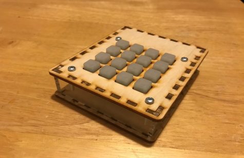
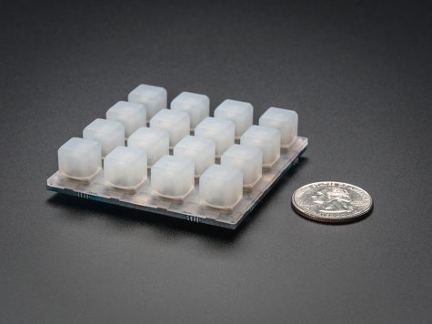
The finished product
I will be making a MIDI pad with an Arduino Elegoo circuit board. For those who don’t know, a MIDI pad generates and transmits MIDI data to MIDI enable devices. The simplified version: a MIDI pad is used in electronic music making to simulate beats and sounds. It is extremely useful for creating unique beats. With this design, I will be able to program whatever sounds I want into the MIDI Pad, whether it be low bass or high piano music.
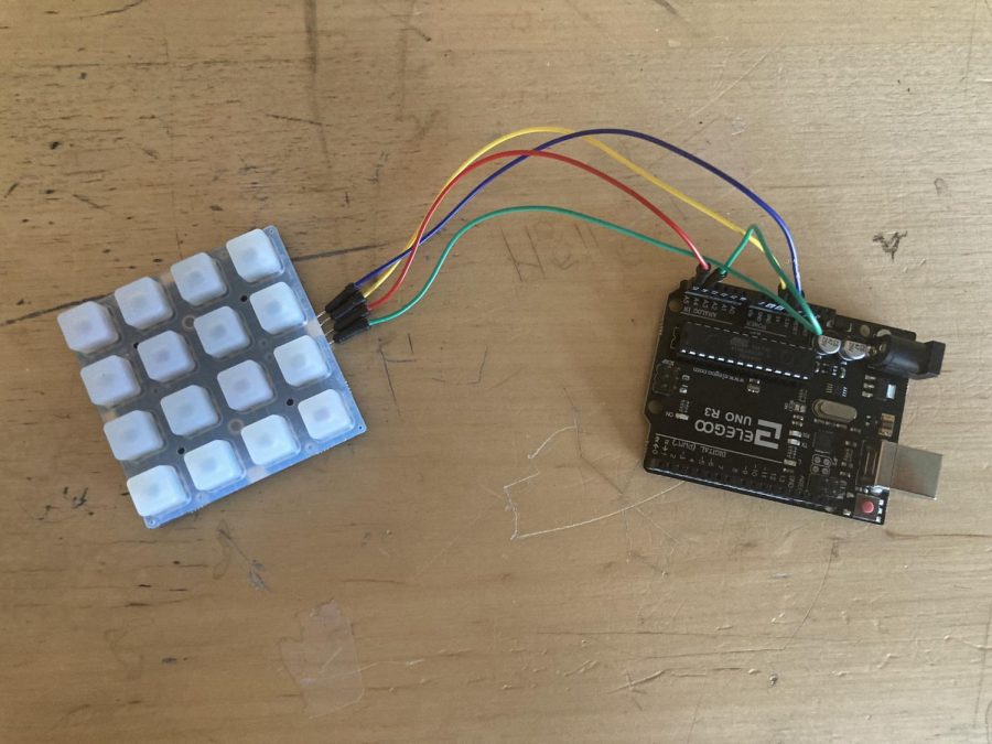
To the side is an image from one of the sets of instructions that I will be following. Mine won’t be the same, but it will be similar. For example, instead of just adding the same color of LEDs that the directions call for, I’ll be using RGB LEDs. In addition, the design of the pad won’t be exactly the same. For example, I won’t be making a frame for it. Instead, I’ll just make the raw components.
With that being said, the tools I’ll need are quite simple. I’ll need:
– A Soldering Iron
– Solder
There really isn’t that much to it in regard to the tools that I will be using.
The list of materials is as follows (Based on NathanL111’s Instructables.com article):
– 1x Elegoo Arduino Uno R3
– 1x Trellis Keypad Base
-1x Elastomer 4×4 Keypad
– 16x multicolored LEDs (3mm)
-4x jumper cables
While the supplies are arriving, I will be writing the code. I will be copying this from the first set of instructions listed in the Related Articles section; however, if needed, I might mix and match different parts of the code from the first and second sets to improve performance.
The process to make the MIDI pad is quite simple. The first thing I’ll need to do is solder the LEDs to the Trellis
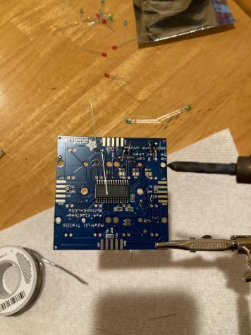
keypad. To do so, all I needed to do was to stick the LEDs into the specified holes on the base of the Trellis keypad. There are markings that tell you which leg of the LED goes where. Then I folded the legs down, soldered them, and snipped the legs to roughly 3mm. I did this for all 16 of the buttons.
The next thing that I did was solder the jumper cables. There are tiny gold stripes on all 4 sides of the Trellis base. These are what I soldered the jumper cables to. Only soldering on one side of the base, I attached one cable to SDA, another to SCL, one more to GND, and
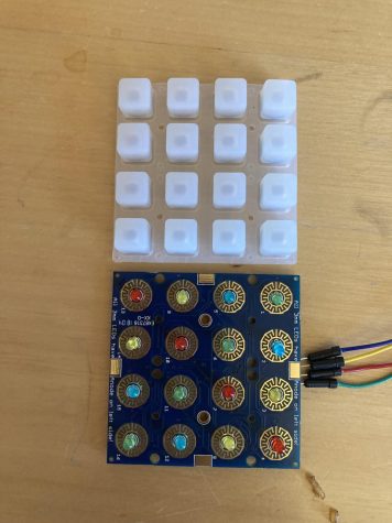
the last one to 5v. After that, all that was left was to put the elastomer 4×4 keypad on the top and voila! The keypad was finished!
The last step is to connect the keypad to the Arduino. Simply connect SDA to A4, SCL to S5, 5V to 5V, and GND to GND. Upload the code and the project is complete!
To make music with the MIDI pad, you need to download Hairless MIDI. Currently what the project does is it sends MIDI data through the serial port. What Hairless MIDI does is it formally converts the serial data into MIDI data. In short, it allows music making software like GarageBand and Abelton to register your brand new MIDI pad as a MIDI device. Once it is on your computer, you are ready to make music!
RELATED ARTICLES