Arduino Uno R3 Elegoo Controlling A DC Motor With A Joystick Project
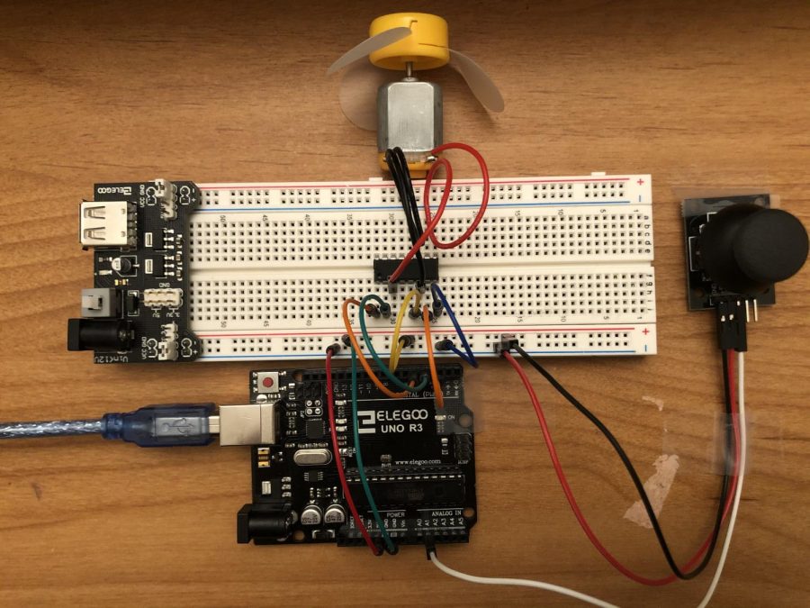
Today I will be making the arduino uno r3 elegoo controlling a DC motor with a joystick project. The materials you will need for this project are, 7 breadboard jumper wires, 3 female-to-male dupont wires, 1 DC motor, 1 joystick, 1 power supply module, 1 L293D, 1 USB cable, 1 breadboard and 1 uno r3 controller board. The direction for this project will be located below so you can follow along.
Step 1: Get your first breadboard jumper wire and connect it to pin “5V” on the uno r3 controller board, and connect the other end of the breadboard jumper wire to the negative rail on the breadboard.
Step 2: Get your second breadboard jumper wire and connect it to pin “GND (Ground)” on the uno r3 controller board, and connect the other end of the breadboard jumper wire to the positive rail on the breadboard.
Step 3: Get your third breadboard jumper wire and connect it to pin “~5” on the uno r3 controller board, and connect the other end of the breadboard jumper wire to pin “j32” on the breadboard.
Step 4: Get your fourth breadboard jumper wire and connect it to pin “4” on the uno r3 controller board, and connect the other end of the breadboard jumper wire to pin “j31” on the breadboard.
Step 5: Get your fifth breadboard jumper wire and connect it to pin “~3” on the uno r3 controller board, and connect the other end of the breadboard jumper wire to pin “j26” on the breadboard.
Step 6: Get your sixth breadboard jumper wire and connect it to the positive rail on the breadboard, and connect the other end of the breadboard jumper wire to pin “j28” on the breadboard.
Step 7: Get your seventh breadboard jumper wire and connect it to the negative rail on the breadboard, and connect the other end of the breadboard jumper wire to pin “j25” on the breadboard.
Step 8: Get your first female-to-male dupont wire and connect it to pin “A1” on the uno r3 controller board, and connect the other end of the female-to-male dupont wire to pin “VRx” on the joystick.
Step 9: Get your second female-to-male dupont wire and connect it to the negative rail on the breadboard, and connect the other end of the female-to-male dupont wire to pin “+5V” on the joystick.
Step 10: Get your third female-to-male dupont wire and connect it to the positive rail on the breadboard, and connect the other end of the female-to-male dupont wire to pin “GND” on the joystick.
Step 11: Now get your power supply module and connect it to the far left of the breadboard.
Step 12: Get your L293D and connect the right side of it through the pins “f25” to “f32” on the breadboard and connect the left side through the pins “e25” to “e32” on the breadboard.
Step 13: Now connect the positive wire from the DC motor to pin “g30” on the breadboard, and connect the negative wire from the DC motor to pin “g27” on the breadboard.
Step 14: Connect your project to your computer using the USB cable and download the code which is located below.
Now that you are finished with installing the code your “arduino uno r3 elegoo controlling a DC motor with a joystick” project should work as you move the joystick from side to side.
Code for project-
//www.elegoo.com
//2018.8.20
/*
This example use the Y-axle of joystick to control the DC Motor
*/
const int Y_pin = 1; // analog pin connected to Y output
#define ENABLE 5
#define DIRA 3
#define DIRB 4
int i;
void setup() {
//—set pin direction
pinMode(ENABLE,OUTPUT);
pinMode(DIRA,OUTPUT);
pinMode(DIRB,OUTPUT);
Serial.begin(9600);
}
void loop() {
long y;
y = analogRead(Y_pin);
Serial.print(“val=”);
Serial.println(y);
if(y == 0){
analogWrite(ENABLE,255);
digitalWrite(DIRA,LOW); //one way
digitalWrite(DIRB,HIGH);
}
if(y>0&&y<100){
analogWrite(ENABLE,200);
digitalWrite(DIRA,LOW); //one way
digitalWrite(DIRB,HIGH);
}
if(y>100&&y<250){
analogWrite(ENABLE,180);
digitalWrite(DIRA,LOW); //one way
digitalWrite(DIRB,HIGH);
}
if(y>250&&y<400){
analogWrite(ENABLE,128);
digitalWrite(DIRA,LOW); //one way
digitalWrite(DIRB,HIGH);
}
if(y>400&&y<500){
analogWrite(ENABLE,80);
digitalWrite(DIRA,LOW); //one way
digitalWrite(DIRB,HIGH);
}
if(y>500&&y<600){
analogWrite(ENABLE,0);
digitalWrite(DIRA,LOW); //one way
digitalWrite(DIRB,HIGH);
}
if(y == 1023){
analogWrite(ENABLE,255);
digitalWrite(DIRA,HIGH); //revers
digitalWrite(DIRB,LOW);
}
if(y>923&&y<1023){
analogWrite(ENABLE,200);
digitalWrite(DIRA,HIGH); //revers
digitalWrite(DIRB,LOW);
}
if(y>800&&y<923){
analogWrite(ENABLE,180);
digitalWrite(DIRA,HIGH); //revers
digitalWrite(DIRB,LOW);
}
if(y>700&&y<800){
analogWrite(ENABLE,128);
digitalWrite(DIRA,HIGH); //revers
digitalWrite(DIRB,LOW);
}
if(y>600&&y<700){
analogWrite(ENABLE,80);
digitalWrite(DIRA,HIGH); //revers
digitalWrite(DIRB,LOW);
}
}