How to Build a 10-Meter LED Display Using Elegoo Arduino Uno R3
Today, I’m going to teach you how to build a giant wall of LED that can display pictures, videos, and GIFs that you program onto it. Here are the Supplies you need to get started
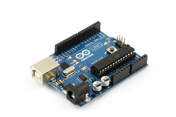
1. An Arduino Uno (no surprise there) https://store.arduino.cc/usa/arduino-uno-rev3?gclid=CjwKCAjw_sn8BRBrEiwAnUGJDkHZt_LJ7JtlgOoY1ThGCw8uYKvBFvb701gPmmD9wI5_eialNJKZnxoCqzMQAvD_BwE
2. 10 meter strip (sold in two 5 meter strips) of 60 LED pixels. I recommend WS2812B because they are cheap. https://www.aliexpress.com/item/2036819167.html
3. 5V 10A power supply. This model needs 240V AC to input screw terminals. If you want a safer, but more expensive approach, use an inclosed modal. https://www.amazon.com/Visdoll-AC100-240V-Transformers-Switching-Adapter/dp/B07424TY42/ref=asc_df_B07424TY42/?tag=hyprod-20&linkCode=df0&hvadid=242074892521&hvpos=&hvnetw=g&hvrand=108199362874275148&hvpone=&hvptwo=&hvqmt=&hvdev=c&hvdvcmdl=&hvlocint=&hvlocphy=9008135&hvtargid=pla-407263698439&psc=1
4. an Ikea RIBBA, deep photo frame 50cm x 50cm with glass to fit in the frame. https://www.ikea.com/qa/en/p/ribba-frame-white-20378440/
5. Glass frosting spray and white spray paint https://www.amazon.com/Rust-Oleum-257465-11-Ounce-Specialty-Frosted/dp/B004M5B4U4/ref=sr_1_2?dchild=1&gclid=Cj0KCQjwreT8BRDTARIsAJLI0KIS5JII4l5_jW45FIRJmPn9lHF_H8kbCj8nU9VtuiVRO-Xj2tqqA6UaAk_2EALw_wcB&hvadid=177808219117&hvdev=c&hvlocphy=9008135&hvnetw=g&hvqmt=e&hvrand=5469253657813361206&hvtargid=kwd-1707461560&hydadcr=8457_9883267&keywords=glass+frosting+spray&qid=1603906357&sr=8-2&tag=googhydr-20 https://www.amazon.com/RUST-OLEUM-331181-Painters-Touch-White/dp/B0787D8PYT/ref=sr_1_3?dchild=1&keywords=White+spray+paint+for+glass&qid=1603906391&sr=8-3
6. multiple lengths of THICK wire. have a wire cutter handy https://www.target.com/p/liberty-19-gauge-picture-hanging-wire/-/A-14894023?ref=tgt_adv_XS000000&AFID=google_pla_df&fndsrc=tgtao&DFA=71700000012764136&CPNG=PLA_Home%2BImprovement%2BShopping_Local&adgroup=SC_Home%2BImprovement&LID=700000001170770pgs&LNM=PRODUCT_GROUP&network=g&device=c&location=9008135&targetid=pla-896314107298&ds_rl=1246978&ds_rl=1247068&ds_rl=1248099&gclid=Cj0KCQjwreT8BRDTARIsAJLI0KJ7W8V8sBA3aJ-S6zBWCTii_hf7Nkn1V_x0g2JH5S7L5pCPRHK47qkaAq0JEALw_wcB&gclsrc=aw.ds
7. A hot glue gun, Scolding iron and solder, scissors or a knife, wire stripper.
Now to the instructions. First, do the math. Cut 15 strips of led lights to place into the photo frame, if you cant fit them ALL in that’s fine, just do as much as you can.
Then, coat your glass with the frost spray on both sides, with an even amount. Make sure you don’t scratch or crack your glass. Then cut off one of the corners for the power and signal wires.
Next, you want to take your cut LED strips and your glue gun and glue your LED strips on. Now the glue gunner is VERY hot so be careful and let it cool. You don’t want to much glue as that will get sticky. If it needs a little more support, just grab some clear tap and stick it on, don’t go crazy with it though. Remember that the signal will snake around from the start to finish, and that there is a specific direction to each strand. Lay one with the arrow pointing right, then the following strand going to the left, and repeat. Double check this before gluing them down!
You are going to need 3 wires all of slights different lengths to be connected. In each case, you will be connecting the two inner most pads with the shortest length of wire, and then the middle two, then the outer two with the longest length. The inner most pad is going to be between the +GND line, and the +5V line depending on which side of the frame you’re working on.
Be sure both to pre-solder both the wires AND pads. This is the most time wasting ordeal of the project, but it’s VERY important you don’t rush and double check you’re connecting the correct lines!
Now you are going to connect it to you Arduino.
To connect the LED’s to the Arduino is simple actually; while the 5V power into the LEDs should come directly from your external power supply. Then, take your power supply, Arduino, and find the common ground wire, and connect them. DO NOT TRY TO POWER THE LED STRAND DIRECTLY FROM THE ARDUINO, OR CONNECT THE 5V POWER SUPPLY TO THE ARDUINO WHEN THE USB IS CONNECTED (it will be updated to the code)
Then download and add the Adafruit NeoPixel library to your Arduino folder. then launch the Arduino. Perform an initial strand test using the example strandtest code included in the library. Adjust the number of LEDs you have in the first parameter of the following line (change 60 to however many): Adafruit_NeoPixel strip = Adafruit_NeoPixel(60, PIN, NEO_GRB + NEO_KHZ800);If the animation stops at a particular row, unplug it immediately and check the wiring. You’ve either got the strand in the wrong direction; the wires are crossed; or you accidentally soldered the +5V to the GND.
Then, connect the glass to the frame in any way you like. I recommend using the hot glue gun, but any way you want works. Make sure not to crack your screen. Cut a hole in the back corner (any corner works) of the screen, large enough to fit the thick wires. If you followed the instructions , your LED lights should turn on now. To know more of how to connect them to Arduino and to display picture, click this link here and start at STEP 7. https://www.makeuseof.com/tag/weekend-project-build-giant-led-pixel-display/
Related Stories
https://create.arduino.cc/projecthub/karmette/basic-led-setup-for-beginners-0a124a
https://create.arduino.cc/projecthub/rowan07/make-a-simple-led-circuit-ce8308
https://www.instructables.com/Controlling-Multiple-LEDs-With-an-Arduino-Uno/